diamond drill hole

Water Cutoff in an Open Diamond Drill Hole

Case description

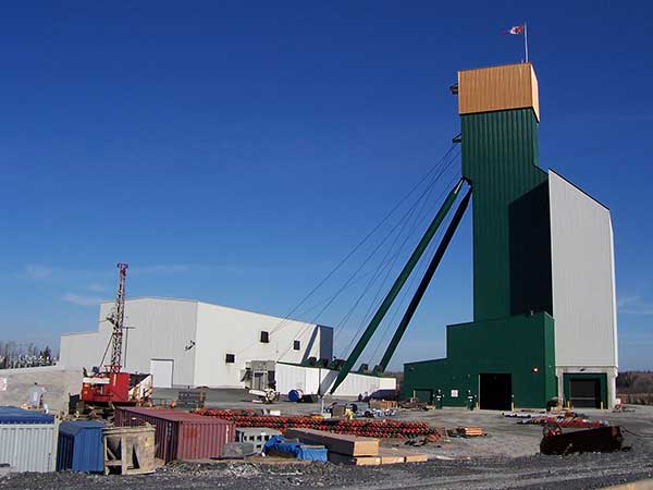
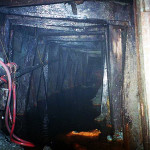
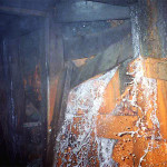
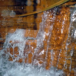
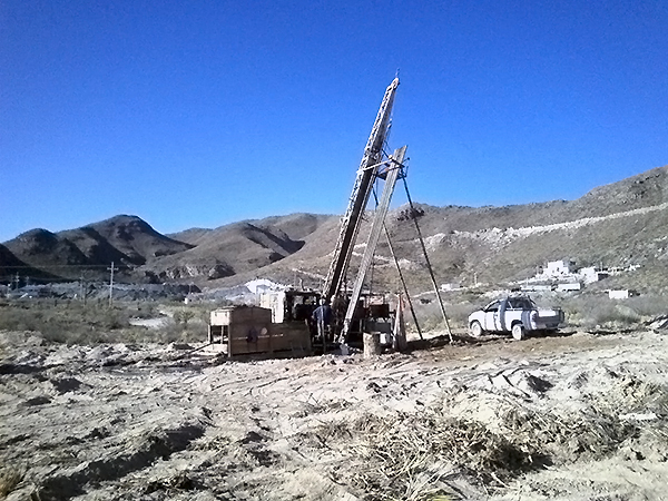
A mining contractor was developing an underground ramp through otherwise competent rock conditions when blasting exposed an ungrouted diamond drill hole from the surface that flooded the heading a substantial distance from the face.

The mining company engaged Peter White to travel to the site and supervise grouting operations to seal the flowing drill hole so that ramp development work could resume.

Solution

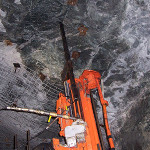
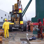
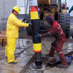
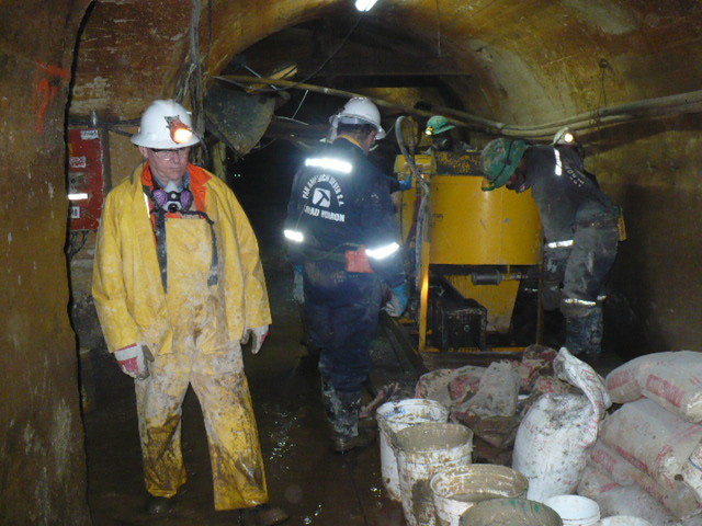
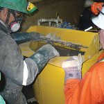
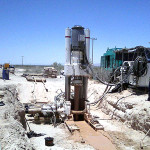
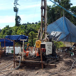
After assessing site conditions, Peter worked with contractor personnel to rig a rock bolt jumbo to mechanically install an inflatable borehole packer within the flowing diamond drill hole. This packer installation procedure was successfully accomplished using the drill jumbo without exposing any personnel to hazards associated with working directly beneath a high volume, cold water inflow.

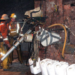
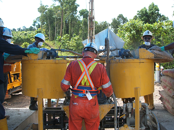
After the packer was installed, a heavy cement grout was mixed on site using 2% calcium chloride as an accelerator. The required grout volume was calculated based upon the drill hole diameter and length.

After the required grout volume had been pumped into the drill hole, a final batch of cement grout was prepared by eliminating calcium chloride and substituting sugar as a retarder to prevent the cement grout from curing within the inflatable packer at the bottom of the borehole.

By observing samples of grout that were collected as the grouting work was underway, Peter was able to determine when the accelerated grout mixture had cured adequately so that mining crews could recover and clean the inflatable packer for subsequent use.

Mining crews were then able to resume regular development activities within the ramp.
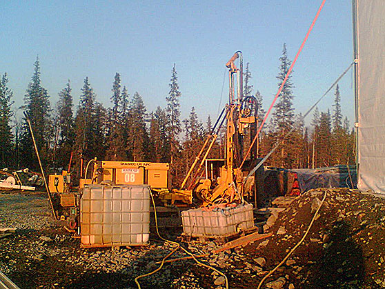
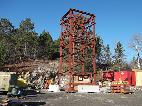
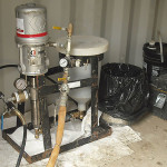
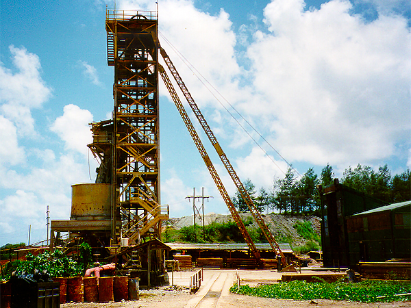
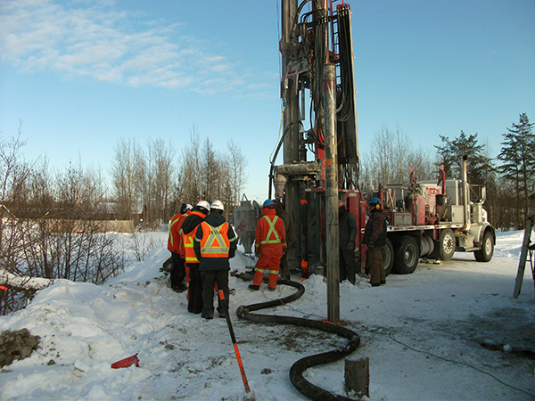
Photo Gallery

Grouting at raise bore pilot hole

Water Cutoff in Raise Bore Pilot Hole

Case description

A gold mining company had pre-drilled a 380 mm diameter raise bore pilot hole from surface to a depth of 600 m when it was discovered that water-bearing rock fractures were allowing groundwater to enter the pilot hole at a depth of 122 m below surface.

Project engineers requested Peter White to devise a suitable grouting plan and supervise their contractor’s crews to eliminate the water inflow prior to reaming the ventilation raise to full diameter.

Solution

Peter designed a diamond drilling layout to intercept the water-bearing fractures from the surface. Completed drill holes were gyro-surveyed so that drill hole locations were established for planning subsequent drill holes.

A large diameter inflatable packer was suspended within the pilot hole below the water-bearing fractures and inflated to allow the pilot hole to fill with water and eliminate water flow down the pilot hole. Filling the pilot hole with water enabled cement grouting of the water-bearing fracture to be accomplished under no-flow conditions.

Water testing and evaluation of drill cores established that aperture size of the water-bearing fractures was relatively narrow, so Peter determined that microfine cement was the appropriate grouting material for this project.

After drilling and grouting of 12 holes surrounding the ultimate ventilation raise diameter, the inflatable packer was recovered from the pilot hole and it was shown that the residual water flow rate from the pilot hole was negligible, allowing reaming of the ventilation raise to proceed.

Photo Gallery

Publication Article

“Water Cutoff in Raise Bore Pilot Hole” – by Peter White, P.Eng.

Grout Curtain Construction for Ventilation Raise

Grout Curtain Construction for Ventilation Raise

Case description

A gold mining company had pre-grouted around the collar for a new ventilation raise, constructed a concrete foundation and setup a raise boring machine. It was subsequently determined that un-grouted water-bearing fractures within 30 m from surface prevented deeper drilling of the pilot hole.

Company personnel contacted Peter White to arrange a site visit and provide engineering recommendations to resolve the situation by building a grout curtain so that pilot hole drilling could resume.

Solution

After assessing the site conditions and requirements, Peter developed designs and specifications for additional drilling and cement grouting work.

After the drilling and grouting contractor had mobilized to site, Peter returned to supervise cement grouting operations. Work proceeded by systematically drilling widely spaced primary holes utilizing top-hammer percussion drilling equipment and grouting using high-speed colloidal grout mixers.

Drilling and grouting work continued with secondary and tertiary holes to gradually close spacing between adjacent holes until the rock surrounding the ventilation raise had been successfully consolidated and pilot hole drilling could resume.

Photo Gallery


Totten Mine Sudbury manway

Water Cutoff in Raise Bore Manway

Case description

A mining contractor was working down from the surface using an Alimak raise climber to install ground support prior to equipping an emergency escape manway inside a 2.4 m diameter raise bore hole to a depth of 400 m. Cumulative water inflow of
50 USGPM from fractured ground conditions at various locations created wet and slippery conditions for contractor personnel working inside the raise during winter conditions.

Solution

Based on previous success with a similar manway installation project, the mining contractor contacted Peter White for engineering support, chemical grouting equipment, accessories and materials, as well as training of contractor crews, for controlling water inflows and to enable manway installation to proceed.

A turn-key portable shipping container package was provided with auxiliary heating, chemical grouting equipment, materials and accessories that enabled contractor crews to systematically undertake water control operations as required over the depth of the raise.

Grouting equipment and materials were positioned inside the shipping container on surface and chemical grout was transferred down the raise “on demand” using long high-pressure hoses with appropriate high-pressure control valves installed at the active work location. Peter designed the high-pressure chemical grout equipment, hoses and associated hardware to enable the mining crews to delivery chemical grout over a distance of several hundred meters.

Contractor crews successfully completed water control work in conjunction with the installation of ground support (bolts and screen) in preparation for manway steel construction.

Project Gallery

Grouting and shaft sinking in Longos mine - Philippines

Shaft Sinking Through Water-bearing Ground

Case description

The sinking of a new shaft at an established gold mine was interrupted due to flooding by a blow-out at the shaft bottom while in the process of installing a grout curtain. Initial attempts at shaft recovery were unsuccessful and further shaft sinking was abandoned for several years.

After a subsequent change in company management, Peter White was invited to assess the site conditions and determine if the water inflow could be stopped to enable shaft sinking operations to resume.

Solution

Peter determined that the shaft could be salvaged by accessing the original blow-out location at shaft bottom and preparing the site for water cut-off grouting operations.

Shaft crews worked in water inflow conditions of 800 USGPM to recover the shaft bottom, remove debris and fractured rock, install drainage pipes and pour new concrete at the shaft bottom. Upon completion of this preparatory work, the original shaft bottom inflow had been reduced to 30 USGPM.

Cement grouting equipment was installed at the shaft collar and long grout delivery pipes were attached to the shaft lining. Sodium silicate grouting equipment was installed at a shaft station approximately 30 m above the shaft bottom.

Shaft bottom grouting work consisted of simultaneous injection of cement grout and sodium silicate to produce a fast curing grout mixture. After many months of preparation work, shaft bottom grouting work required several hours to successfully seal the primary water flow channels and permanently reduce the water inflow rate.

Subsequent drilling and cement grouting operations were undertaken to seal the fractured rock strata surrounding the shaft bottom, as well as below the floor of the shaft prior to resuming shaft sinking.

Photo Gallery

Download Publication

water control in shaft construction

Water Control for Shaft Construction

Case description

Shaft construction associated with a mine expansion project was stopped when 1,200 GPM of water inflows were encountered within an aquifer zone at a depth of 43 meters below the 250 meter level at underground silver mine.

The mining company contacted Peter White to provide engineering direction to overcome the water inflow, supply specialized grouting equipment and accessories, as well as to provide on-site training for company crews to undertake the required drilling and grouting work.

Solution

To overcome the water inflow situation, Peter designed a systematic drilling and cement grouting program using long diamond drill holes collared from the underground 250 level that extended to the planned bottom of the mine shaft for a cement grouting operation to minimize water inflows for future shaft sinking, associated level development and loading pocket construction.

The grouting program involved cement grouting to reduce high volume water inflows through fractured rock and water-bearing ground conditions. Regular Portland cement was mixed at a W:C ratio of 2 by weight of cement, as thicker grout mixtures would not penetrate the water-bearing aquifer formation.

Cement grouting equipment supplied by Peter included a double-drum grout mixer and high-pressure plunger pump rated for the volumes and pressures required to undertake the project, as well as an electromagnetic grouting flowmeter, in-line diaphragm pressure sensors and liquid-filled pressure gauges.

Initial reductions in water inflow rates were observed after completing primary hole drilling and grouting operations. Subsequent secondary and tertiary holes were drilled and grouted to close in the spacing between adjacent drill holes, resulting in the successful overall reduction of water inflows that enabled resumption of shaft sinking activities.

Photo Gallery

Alimak Raise Water Cutoff

Alimak Raise Water Cutoff

Case description

While driving a vertical Alimak pilot for the construction of a large diameter ventilation raise, a mud slip was encountered that resulted in a large volume water inflow situated approximately 100 m up the raise and 200 m below surface.

The gold mining company contacted Peter White to provide hands-on engineering direction of Alimak crews to stop the existing water inflow and to improve ground conditions prior to resuming ventilation raise construction.

Solution

Peter provided comprehensive training for all of the Alimak crews to safely use chemical grout for water cutoff work. In addition, Peter provided training to contractor’s mechanics for maintenance and servicing of all grouting pumps and equipment.

An initial stage of chemical grouting was undertaken to stop the initial high-volume water inflow. After drilling shallow probe holes into the water flow path, chemical grout and pumping equipment were moved to the top of the raise using the Alimak climber.

Subsequent stages of systematic deep hole drilling with cement grouting were undertaken to displace water away from the future ventilation raise. After drilling deep holes from the Alimak platform, long high-pressure grout hoses were connected to the cement grouting equipment situated at the bottom of the raise.

Alimak crews successfully completed chemical and cement grouting stages of work over several weeks to eliminate water seepage in preparation for subsequent excavation and concrete wall construction.

After completion of all grouting work, the mud slip area was excavated to final diameter and reinforced by constructing a concrete wall prior to continuing the Alimak pilot raise to the surface.

Photo Gallery


water control underground karst limestone

Water Cutoff in Underground Karst Limestone

Case description

A high-grade underground silver mine was operating below the water table within a karst limestone formation that included numerous faults and other water-bearing structures.

Potential water inflows were controlled by drilling probe holes and injecting cement prior to advancing development and production headings.

While reaming a new ventilation raise, the reamer encountered an un-grouted fracture that resulted in a high volume water inflow of approximately 40,000 USGPM that rapidly flooded the mine workings.

Solution

The mining company contacted Peter White to direct mine recovery operations.

Surface exploration drill rigs were used to drill three holes that intersected locations near the water inflow.

Peter worked with a local ready-mix supplier to formulate a cohesive cement-sand grout mix to fill the mine openings beneath the water inflow location. A conventional concrete pump truck was used to deliver several ready-mix truckloads of cement-sand grout to fill the ventilation raise and associated access tunnel.

Surface holes were then re-drilled to verify site conditions and conventional cement grouting operations were undertaken to seal residual water-bearing fractures.

Within a few days after the mine flood event, crews were able to dewater the mine workings and resume mining operations. After additional probe drilling and grouting work near the inflow location, access to the ventilation raise was reopened and the ventilation raise was successfully constructed.

Photo Gallery


ground improvement Ventilation Raise Construction

Ground Improvement for Ventilation Raise Construction

Case description

An underground gold mine was rapidly expanding and urgently required additional ventilation capacity to support the operation of its trackless equipment fleet. Ground conditions were exceptionally poor, with exploration drilling results indicating very low RQD values and many zones with no core recovery.

After geotechnical consultants advised that ventilation raises could not be constructed through such adverse ground conditions, the mining company contacted Peter White to ask if the ground improvement was feasible.

Solution

Based upon Peter’s experience working in similar ground conditions, the mining company decided to proceed with a cement grouting operation to improve ground conditions prior to raise boring the required ventilation raises.

Peter assembled a turn-key grouting plant, complete with ancillary equipment and accessories for undertaking the planned scope of work, and arranged shipment to the remote mine site in Indonesia.

Ground improvement work involved sequential diamond drilling of 8 holes around the perimeter of each ventilation raise using down-stage methodology. Drilling crews would advance each drill hole stage between 15 to 30 m depending upon ground conditions encountered.

Cement grouting was undertaken using microfine cement to thoroughly penetrate and consolidate fractured ground conditions prior to drilling of the next down stage in each drill hole. Detailed records were maintained of ground conditions encountered, as well as quantity of cement consumed and the applied grouting pressures.

After injecting approximately 40 tonnes of cement along the alignment of each ventilation raise, raise bore crews were able to successfully undertake pilot hole drilling and subsequent reaming to full diameter without difficulty. The excavated ventilation raises remained open without collapse or caving for several weeks until a shotcrete lining was applied.

Photo Gallery

Publication Article

“Ground Improvement for Vent Raise” – by Peter White, P.Eng.

compaction grouting in underground mine

Compaction grouting of underground sinkholes

Case description

A large underground gold mine encountered unstable ground conditions at the surface due to groundwater migration that resulted in the erosion of ground fault structures, widespread surface settlement and occurrence of sinkholes aligned with anomalous sub-surface soil/rock geometry.

Prior to engaging Peter White’s grouting engineering services, the mining company was relying upon a local contractor to mix and pump a high W:C ratio cement grout using bagged cement materials. This approach to cement grouting involved low productivity and low rates of cement placement.

Solution

The mining company immediately implemented the recommendations of Peter White and changed over to using low W:C ratio cement grout delivered from local batch plants using ready-mix trucks. This change resulted in an immediate and substantial increase in grouting productivity while reducing overall manpower requirement.

Additional grouting performance improvements were implemented through utilization of thixotropic admixtures to increase the cohesion of bulk cement grout mixtures as delivered from the batch plants.

Peter White subsequently provided suitable mix designs and trained local crews to undertake compaction grouting for critical areas of the site where surface settlement problems were evident.

Photo Gallery