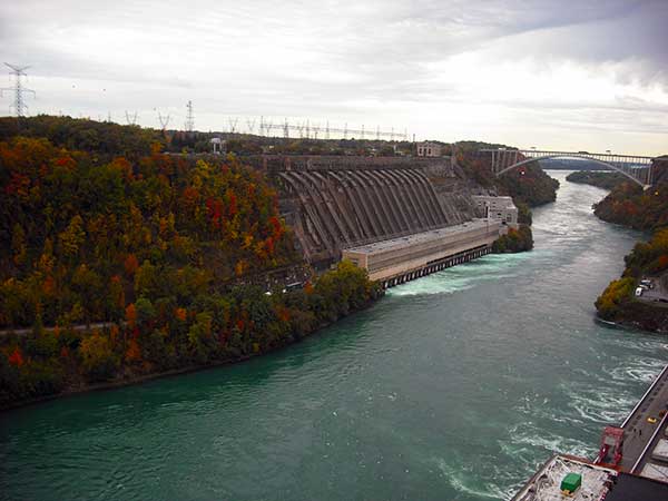
concrete gravity dam

Concrete Gravity Dam Anchor Hole Grouting

Case description

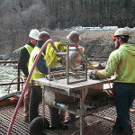
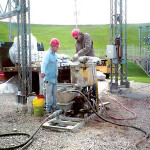
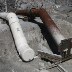
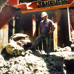
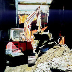
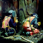
A heavy civil contractor was engaged in anchor installation on an existing concrete gravity dam and encountered difficulty with cement grouting of anchor holes to achieve the required impermeability prior to anchor installation. The contractor had re-drilled and re-grouted some of the same anchor holes several times with unsatisfactory results.

In order to prevent further delays to project schedule and associated increased costs, the project owner retained Peter White for a site visit to join a team of experienced geotechnical engineers to assess site conditions and provide recommendations.

Solution

After an assessment of local conditions, available equipment and construction methodology, it was recommended that the contractor use Type III high-early strength cement to facilitate penetration of small fissures that could not otherwise be achieved using Type I/II Portland cement.

A range of grout mix designs was provided to the contractor that utilized the same basic water-cement content but modified dosages of anti-washout and superplasticizer admixtures to accommodate various water inflow conditions that were anticipated.

Enhancements to the contractor’s grouting equipment included incorporation of appropriate in-line diaphragm pressure sensor and pressure gauge equipment for accurate measurement of grouting pressures. For this project, the owner’s engineer specified that low grouting pressures be utilized, so having accurate pressure measurements was an important control parameter.

The contractor was provided with a detailed step-by-step grouting methodology that covered the range of site conditions that were expected for this site.

Subsequent drilling and grouting operations following this methodology resulted in accelerated preparation of impermeable anchor holes meeting the owner’s specifications.

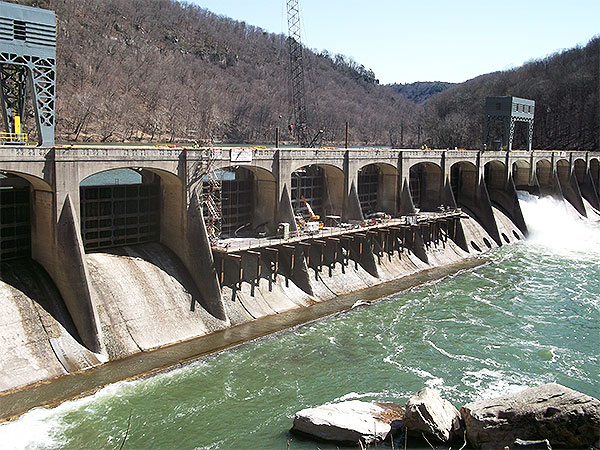
Photo Gallery

water inflows in hydroelectric station

Water Inflows in Gravity Dam Construction Joint

Case description

The Nipawin Hydroelectric Station was constructed in the early 1980’s on the Saskatchewan River. Since that time, SaskPower has experienced problems with significant water inflows entering the headworks drainage gallery through various construction joints.

Solution

Peter White’s specialized engineering services were retained to assess the existing site conditions and prepare technical recommendations for resolving these water inflow problems by chemical grouting.

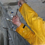
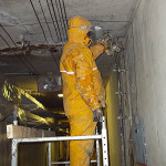
Small diameter core holes were strategically drilled to a depth of several meters to intercept leaking construction joints for investigation, consisting of locating water inflows, measuring flow rates and observing connections between adjacent core holes. Additional holes were drilled as necessary to provide a suitable spacing between adjacent holes prior to the start of chemical grouting operations.

Working during winter when the construction joints were open, the grouting contractor’s personnel, under Peter White’s direction, used water-activated polyurethane grout to systematically reduce and cut-off the major inflows of cold water.

Grouting contractor’s crews successfully completed water control work at various construction joints and reduced the volume of water entering the Nipawin Hydroelectric Station headworks drainage gallery.

Photo Gallery

concrete repairs at hydro facility

Underwater Concrete Repairs at Pumped Storage Plant

Case description

A large pumped-storage hydroelectric power plant required underwater placement of rapid-curing, high-strength concrete to repair the intake structure apron situated at the bottom of the reservoir using barge-mounted concrete mixing and pumping equipment.

Solution

Based upon concrete performance specifications provided by the client’s engineering consultant, various materials and performance-enhancing admixtures were selected working in conjunction with local construction material suppliers.

The contractor assembled the project team and performed trial underwater concrete placement operations to test various concrete mix designs and optimize equipment operations.

Preparation of high-strength concrete was undertaken by a two-stage process of first preparing suitable cement grout mixtures (including all admixtures) using dedicated mixing equipment, followed by transfer of the prepared cement grout to secondary mixers for blending of aggregate materials prior to pumping.

Mixing and pumping equipment with appropriate capacity was selected by our grouting engineer to enable the required underwater scope of work to be undertaken by divers within a time frame of several hours while achieving the required concrete performance for rapid-curing and high-strength.

Photo Gallery

deep dive bypass grouting

Deep Dive Shaft Grouting

Case description

A deep bronze bypass pipe positioned between two adjacent water supply shafts had a defective shut-off valve at a depth of 140 m below surface. The general contractor required the deep bypass pipe to be decommissioned by filling with cement grout that met NSF/ANSI Standard 61 for drinking water system components.

Since the water supply system could only be shut down for brief overnight periods when city water demand was low, diving activities were undertaken using two Atmospheric Diving Suits, with one “suit” working in each of the adjacent shafts in combination with remote submersibles (ROV) that provided lighting and underwater cameras to monitor work activities.

Solution

The first step in planning the deep dive grouting operation by our grouting engineer was to choose suitable grouting materials.  For this project, Type I/II Portland cement and ground granulated blast furnace slag (GGBFS) were selected, both of which conformed to NSF/ANSI Standard 61.  No other additives or admixtures were required for this grout mixture.

The second step was to configure appropriate cement grouting equipment to prepare a consistent high-quality grout mixture, provide for redundancy of critical equipment components and incorporate variable frequency drives to facilitate rapid and controlled adjustment of grout flow rates and grouting pressures.

The third step in planning the deep dive grouting operation was to select an appropriate grouting hose for transfer of mixed grout from the surface grouting plant to the point of injection at a depth of 140 m below surface.

After months of detailed preparations, hundreds of diving hours using the Atmospheric Diving Suits, and several days undertaking mockup trials, the grouting operation supervised by our grouting engineer was successfully completed in less than 3 hours from start to finish.  The day following the underwater grouting operation, diving crews recovered grouting manifolds from the shaft bottom that were plugged solid with cured cement grout – a positive indication of the state of the sealed bronze bypass pipe.

Photo Gallery

Publication Article

“Deep Dive Shaft Grouting” – by Peter White, P.Eng.

cofferdam construction

Cofferdam Construction in Faulted Ground Conditions

Case description

Construction of a run-of-river hydroelectric power plant required an extensive cofferdam to be built within a steep river valley aligned with a major regional fault structure. Cofferdam construction was at risk of being undermined through porous rock formations during the summer runoff season when high water levels flow through the river valley.

Solution

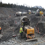
The contractor used overburden drilling equipment to install casing and systematically drill open holes using down stage drilling techniques as deep as 25 m below surface. Adjacent drill holes were sequentially positioned following primary, secondary and tertiary spacing.

High-density cement-flyash grout was delivered to site from a central batch plant using ready-mix trucks and pumped through drill casing using small concrete pumps to achieve high rates of grouting performance while monitoring grout delivery volumes and pressures.

Drilling and grouting operations proceeded on a split spacing pattern to consolidate faulted and porous ground conditions and to strengthen foundation conditions beneath the cofferdam.

Cofferdam remained intact during summer runoff and provided suitable working conditions for ongoing construction work within the cofferdam area.

Photo Gallery

Publication Article

“Large Scale Cement Grouting for Forrest Kerr Cofferdam Construction” – by Peter White, P.Eng.

water cutoff in kasrt limes power station niagara

Water Cutoff in Karst Limestone

Case description

An elevator shaft accessing Sir Adam Beck I powerhouse was excavated through karst limestone and shale in the early 1900’s; shaft dimensions are approximately 5 m x 5 m x 60 m deep. Water from the power house forebay intake canal was infiltrating through karst limestone rock formation and entering the brick-lined elevator shaft, creating maintenance problems for elevator equipment and corroding installed structural and electrical components within the shaft.

Solution

A series of large diameter holes were cored through the brick lining to expose the rock walls of the shaft for inspection purposes. It was observed in many locations that loose rock debris had fallen from weak zones and accumulated behind the brick lining.

After reviewing information from adjacent vertical core holes, it was determined that the majority of water infiltration was associated with limestone formations situated near the top of the elevator shaft.

These water-bearing rock formations were isolated from dry rock formations by strategic injection of water-activated polyurethane resin between the brick lining and the shaft rock excavation. Staged drilling and systematic injection of holes at progressively longer lengths displaced infiltrating water away from the shaft wall and gradually reduced active water inflow rates.

Deeper core drilling in conjunction with cement grouting was subsequently used to systematically fill open water flow channels and prevent water from migrating fromthe forebay intake canal towards the elevator shaft.

Water inflow rates as measured at the bottom of the elevator shaft throughout the project were systematically reduced as work was underway and were eventually eliminated. The original water-bearing channels did not propagate or cause water to migrate elsewhere within the elevator shaft.

Photo Gallery


Featured Article

“Overcoming Water Inflow Issues at Sir Adam Beck 1 Generating Station” – by Peter White, P.Eng., Canadian Tunnelling Magazine

deep excavation for soil stabilization

Soil Stabilization for Deep Excavation

Case description

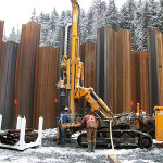
Defective sheet pile walls for a deep excavation project located on the shoreline of Burrard Inlet encountered frequent inrushes of water-bearing soils with development of adjacent sink holes that halted construction of a deep conveyor tunnel. Subsurface site conditions consisted of old dredging spoils from construction of the adjacent Lions Gate Bridge. After site work came to a standstill, our grouting engineer was called to the site to implement grouting operations that would enable site work to resume, as well to provide ongoing engineering support for completion of the remaining excavation work.

Solution

Peter White designed and supervised a $1 million sleeve pipe cement grouting operation to stabilize granular soil conditions beneath and adjacent to the planned deep excavation that enabled excavation work to resume “in the dry”. Supplementary grouting operations were undertaken using water-activated polyurethane resin and various cement grouting additives to tackle occasional inflows that occurred as excavation work proceeded.

Deep portions of the excavation exposed openings in the sheet pile wall, where adjacent sheet piles had split and at some locations where the excavation extended below the bottom of the sheet piles. In these circumstances, the pre-grouted ground conditions were self-supporting and impermeable.

With hands-on engineering support for grouting operations and deployment of various performance-enhancing grouting materials as required, the general contractor was able to complete deep excavation and conveyor tunnel construction as planned.

Photo Gallery