tunnel recovery by cement grouting

Tunnel Recovery Grouting Operations

Case description

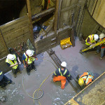
A tunnelling contractor contacted Peter White for technical support and grouting expertise to assist with a tunnel recovery operation to control unexpected water inflows and difficult ground conditions.

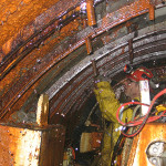
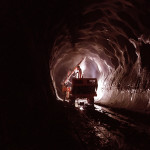
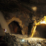
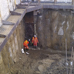
The contractor had successfully excavated approximately 1.5 km of a planned 4 km watermain tunnel with a TBM. Unexpected high volumes of water began to enter at the tunnel face as the TBM passed through a shear plane and ground conditions rapidly deteriorated, so tunnel construction was stopped until remedial measures could be implemented.

Solution

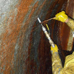
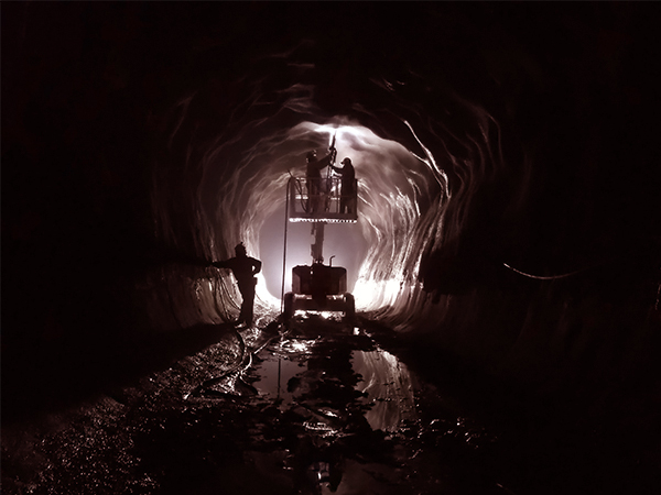
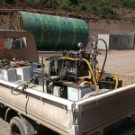
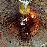
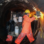
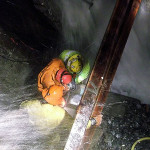
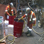
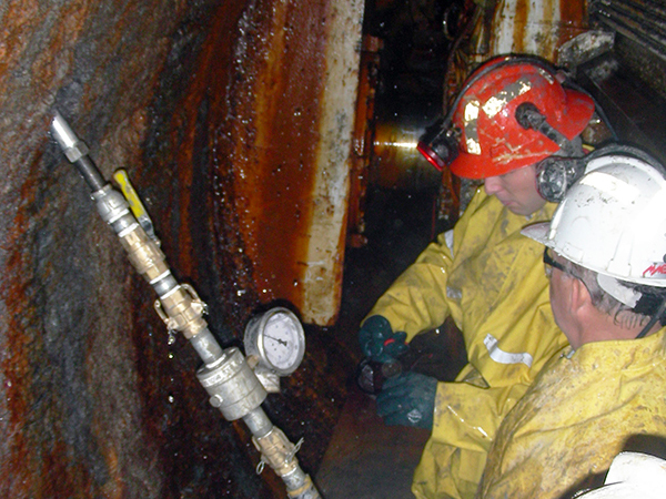
Peter White designed the grouting plan and worked with the tunnelling crew to seal the source of the water infiltration and secure the tunnel face. A series of holes was drilled near the tunnel face for injection of cement and chemical grout.

The grout formulations consisted of both cement and chemical grouts to achieve water control and ground improvement in the vicinity of the TBM.

A cement grout curtain wall was also constructed ahead of the tunnel face to secure the surrounding area prior to future tunnel advancement.

Upon completion of all grouting work, the TBM resumed advance and completed the tunnel without encountering further water inflows.

Photo Gallery

ground consolidation for exploratory drilling

Ground Consolidation for Exploratory Drilling

Case description

One of the longest highway tunnel projects in the world required long horizontal holes to be drilled in advance of the tunnel face to explore geology ahead of the tunnel face.

The ground conditions were severely fractured and local drilling contractors were unable to penetrate beyond 100 m ahead of the tunnel face.

Solution

One of the local drilling contractors engaged Peter White to travel to Taiwan and to direct cement grouting operations in support of his horizontal drilling operation. Since it was not intended to undertake widespread rock grouting in advance of tunnel operations, the contractor’s requirement was only to stabilize ground conditions near the borehole to facilitate drilling operations.

Peter formulated a rapid-curing, high-density cement grout that also included 2% calcium chloride as an accelerator. With ambient temperature conditions of approximately 300C, the cement grout mixture cured within approximately 30 minutes after grouting.

Inflatable packers were used to isolate the bottom ungrouted section of the horizontal drill hole, to minimize the length of re-drilling when the contractor resumed the next stage of drilling.

By implementing the cement grouting system designed by Peter, the contractor was successful in horizontal drilling to depths of 400 to 500 m in each drill hole.

Photo Gallery

Grouting application in tunnel lining

Tunnel Lining Reinforcement

Case description

The intake water supply tunnel for a hydroelectric station was constructed with shotcrete ground support and a spray-on lining to minimize water loss from a high-pressure section of the tunnel constructed through weak ground conditions.

Routine inspection of the tunnel revealed that the spray-on lining had failed at certain locations, allowing water seepage to escape from the tunnel during power plant operation.

The project owner retained Peter White to develop an appropriate repair methodology and to supervise grouting work by a local contractor.

Solution

Following a site visit, Peter provided a suitable drilling pattern to accommodate specific deficiencies observed in the spray-on tunnel lining.

Initial test work was undertaken with candidate injection materials and a two-component urethane elastomer was selected that provided performance characteristics that best suited the site conditions.

Peter worked closely with the contractor’s injection crew to undertake the required chemical grouting work, monitoring injection volumes, grouting pressures and connections with adjacent drill holes and defects in the spray-on lining.

Photo Gallery

water cutoff using chemical grouts

Water Cutoff using Chemical Grouts

Case description

A tunneling contractor excavated a long sewer tunnel by dewatering the ground and using a TBM with steel ribs, filter fabric and wood lagging for temporary tunnel support. The contractor would occasionally encounter quicksand conditions that would breach the temporary tunnel support lining and would contact Peter White for emergency support services to regain control of ground conditions and allow tunneling operations to resume.

After completing each stage of tunneling, steel jump forms were used to install a thick concrete lining to complete the sewer tunnel, following which dewatering wellpoints were decommissioned and the external tunnel lining would become pressurized as the water table became re-established.

The contractor experienced numerous water leaks through the concrete lining and contacted Peter White for assistance to rectify these problems.

Solution

Quicksand inflows associated with TBM operations were usually controlled by drilling through the wood tunnel lagging and injecting chemical grout within the tail assembly of the TBM. Depending upon external soil conditions and the degree of ground disturbance encountered, the spacing and sequence of drill holes, as well as the volume of chemical grout injected at each location, were determined on site to stabilize the situation.

Water seepage associated with concrete construction joints required deep drilling of small-diameter holes around the circumference of the sewer pipe, followed by systematic injection of water-activated chemical grout to seal available apertures.

Photo Gallery

Tunnel Water Inflow Recovery

Water Inflow Recovery in a Tunnel Construction Project

Case description

An unexpected water inflow of 1500 USGPM interrupted underwater tunnel construction for a hydroelectric expansion project when an open fracture was encountered that flooded the face of the tunnel and suspended further work until this high-volume inflow could be stopped.

The general contractor requested that Peter White come to the project site and provide hands-on direction of tunnel recovery activities.

Solution

Site inspection revealed that the 1500 USGPM water inflow was associated with a single open rock fracture that was connected to an unlimited water supply from an adjacent lake.

The first stage of recovery was to install several grouting pipes into the flowing aperture, following which a site-fabricated, steel water control gate was installed to cover the aperture location. A temporary wooden sluice was installed through the gate structure to divert as much water as possible through the open gate while subsequent preparations were made.

The perimeter of the steel gate structure was then sealed back to the adjacent rock surface using quick-setting hydraulic cement and water-activated chemical grout that enclosed additional large diameter drainage pipes. After the perimeter seal was in place, formwork was constructed and the steel gate structure was enclosed in concrete.

Prior to the start of cement grouting operations, valves attached to the large diameter drainage pipes were closed, the temporary wooden sluice was removed from the gate and the steel gate was closed and secured. After closing the gate, all of the water flow was stopped, so the only remaining requirement was to fill the water-filled fracture behind the gate.

A high density cement grout was prepared using conventional grouting equipment, with 2% calcium chloride accelerator, and pumped through the available grouting pipes. After placing several cubic meters of high density cement grout behind the steel gate, grouting operations were suspended and the cement grout was allowed to cure.

The following day, probe holes were drilled and confirmed that all open fractures had been sealed by the cement grouting operation.

Photo Gallery

Publication Article

“Tunnel Water Inflow Recovery” – by Peter White, P.Eng.

deep shaft construction jobsite toronto

Deep Shaft Construction through Quicksand Soil Conditions

Case description

Construction of a deep shaft for repair of the Coxwell Trunk Sewer encountered ultra-fine quicksand soil conditions at the interface between the original tunnel lining and shaft excavation that could not be dewatered using conventional well points.

Shaft wall construction consisted of secant piles down to the top of existing sewer tunnel, with subsequent jet grouting to close residual areas surrounding and beneath the existing sewer tunnel. Due to complex geometry at the shaft lining to tunnel lining interface, residual layers of ultra-fine soils remained under high hydrostatic water pressure that flowed into the shaft excavation and delayed construction work.

Solution

Based upon past experience with other similar projects, Peter White developed a drilling and grouting plan involving sodium silicate injection, in conjunction with the use of water-activated polyurethane resin, to systematically consolidate and stabilize water-bearing, ultra-fine soils so that shaft excavation could proceed in a safe and controlled manner.

Shaft excavation crews, with assistance from Peter White’s technical personnel, were able to successfully stabilize quicksand conditions and proceed with the remaining excavation work required to complete construction of the Coxwell Trunk Sewer Bypass.

Photo Gallery