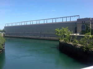
In 1917, work began on the largest construction project undertaken in North America at that time: construction of the hydropower plant now known a Sir Adam Beck 1 Generating Station at Niagara Falls, Ontario, employing 10,000 workers. After four years of difficult work, the plant opened on December 28, 1921.
One part of this complex construction project was an elevator shaft more than 60 metres deep that provides access from the top of the generating station to a tunnel connecting with the power station. This elevator shaft was blasted through shale and limestone formations with a cross-section of approximately 5.5 m x 5.5 m.
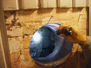
The lower section of the elevator shaft was constructed with an internal concrete liner that provided an inside cross-section of approximately 4.2 m x 4.2 m. The upper section was constructed with a lining using several layers of brick to provide the same cross-section. Eight vertical chimney drains were constructed behind the concrete and brick lining – two drains behind each wall of the elevator shaft – to allow groundwater seepage to drain to the bottom of the elevator shaft where a horizontal drain pipe directed water inflows to the Niagara River.
Over time, water inflows began to sheep through the brick lining at various locations, leading to corrosion of the support steel for the elevator compartment. Crumbling shale blocked several of the vertical chimney drains and further compounded water inflow problems.
Numerous efforts were made over the years to minimize de advert effects of water inflows. By 2009, approximately 100 cubic metres of water was entering the elevator shaft each day, contributing to wet conditions at the bottom of the elevator shaft and impeding the operation of the elevator. OPG engaged the services of Multiurethanes, working in conjunction with Newman Brothers and various subtrades, and KGS Group to remedy this situation.

When the project started, one of the difficulties to be overcome was that the site conditions were hidden behind the brick lining, so it was not possible to identify and target specific water inflow locations. OPG personnel who were familiar with the rock formations through which the elevator shaft had been constructed, selected the Decew formation as a likely source of water inflow, so initial work targeted in this area.
Grouting work consisted of several stages that included shallow chemical grouting to a depth of 1.2 m, followed by cement grouting with holes drilled to a depth of 4 m. The initial chemical grouting work resulted in an immediate and significant reduction in water inflow entering the shaft although water was subsequently encountered when deeper holes were drilled for subsequent grouting operations.
By the time that all grouting operations had been completed, residual water inflows entering the elevator shaft from all areas had been reduced to less than 30 cubic metres each day, and nuisance water inflow problems from the targeted area had been eliminated. Read technical paper.
This article was originally published on Canadian Tunneling Magazine.
Peter White is a senior engineer and grouting specialist with over 40 years of experience working with pressure grouting projects around the world.
